Thursday, 29 September 2011

Reference Plates Setup

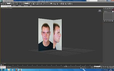
To set up the reference plates I created a plane and then applied a material, with the reference plates bitmap assigned to it, to the plane. I adjusted the self illumination so that the images would not be affected by the lights in the scene.

When I opened the material editor (m) I found  that the slate material editor was being used.

Slate material editor
I went to modes > compact material editor to switch the material editor back to the compact editor.

Compact material editor
I then applied a UVW map modifier to the plane and selected Bitmap fit. I used the gizmo to move the image on the plane to get the image into the right position.

Next I duplicated the plane by holding shift and using the rotation tool. I then adjusted the image on the plane to show the side view of the head, I clicked the flip checkbox in the UVW map modifier to get the image facing the right way.

I positioned the planes so that they were close together but not overlapping. The bitmap image quality in viewports was not high enough so the reference plates were hard to see. I fixed this by going to Customise > Preferences > Viewports > Display Drivers > Configure Driver and then checking match bitmap as closely as possible.


This step was quite straight forward as it was the same way that we were taught to set up reference plates for tank model last year for 3d Modelling and Animation. I also used this method when modelling the objects for the James Bond animation I created.
Tuesday, 27 September 2011

Guidelines and Topology lines

After having prepared the images for the reference plates, the next thing to do was to draw on guides for the topology.

First I started by drawing guidelines onto the image to outline the main features of the face. These guides (blue) were used to help draw the topology guidelines.


Using the guidelines then drawn before I drew the lines for the topology (red). I made sure that there were no quads so that the mesh would deform correctly and there would be no problems with the subdivision. The topology for the nose and top of the eye caused some trouble but by using the video tutorial as a guide this wasn’t too much of a problem.


This part was quite hard and took a long time as I had to make sure that all of the polygons were quads, they flowed correctly and also took account for the shape of the face. Although this was difficult I persevered as planning now will pay off when modelling the head as the topology will be clearly thought out before hand

The reference plates are now finished and will be brought into 3DS Max as a guide for creating the model.

Saturday, 24 September 2011

Preparing Images for Reference Plates

The first task in creating the head model involved creating reference plates. These will be used as a guide when modelling the my head. The process to create these were shown in the first video (http://cg-india.com/tutorials/3dsmax_tutorials_organic_modeling.html)

I started with two photos, one of the front of my head and one of the side. These were brought into Photoshop where they were edited to create the reference plates. The lens correction filter was used to remove the lens distortion in the photo to flatten out the image. Next I copied the two images into the same file and lined them so that the features in the face were level.

This part was quite difficult as all of the features had to be lined up and often some of the features were lined up but others were out of line. I managed to the two images to be resonably aligned and decided to go with them.

Friday, 23 September 2011

First reaction to the brief

This is a blog is for the Virtual Environments module, the module is divided into two tasks that will involve using 3DS Max. This is the second 3D module on the course, the other one being 3D Modelling and Animation (http://abonnington-3d.blogspot.com/). Having used 3DS Max for this earlier module it should be easier to understand as I already know the basis.

Task 1 - Model your own head
The first part of the assignment is to model my head using spline modelling. This will be carried out in the first 5 weeks using a series of video tutorials. This will be 40% of the mark.

I think that this will be interesting as I will be able to learn some organic modelling techniques. The video tutorials should make it quite easy to follow the processes and produce something that looks good. Although I have only looked at the first few videos there are quite a few of them so it looks like there will be lots of steps involved.

Task 2 - Finchingfield Guildhall group project
The second part of the module will take part in the remaing 7 weeks and will involve working in a small group. The task is to visualise the development of grade 1 listed Guildhall in Finchingfield. This will be an animation to show how the Guildhall would have been used or to show how the new building work being carried out will look when finished. There will be a visit to the find more about the project the following week. This will be 60 % of the mark.

This part of the module also seems interesting and I am looking forward to finding out more about this part with the visit. Working in a group will allow differenet parts to be shared out and hopefully allow for a better overall animation to be produced than could be created individually as each person can work on individual parts so more can be created in the set time.