Showing posts with label Model. Show all posts

Monday, 5 December 2011

Hair

Hair was added to the model using the hair and fur modifier. After applying the modifier the whole head is covered in hair. In polygon selection mode within the hair modifer the polygons for where I wanted the hair were selected.


Clicking update selection updates the hair to this selection.


Rendering the hair now shows that it needs to be styled  and the colour changed.


Using the tools for the hair modifier the hair can be cutand styled. Selecting the style hair button allows the tools to be used. I used the cut tool to make the hair shorter.


Next I used the hair brush tool to style the hair. This proved quite difficult as it was hard to get the hair to flow correctly.


Rendering now resulted in the image below.  But the hair is too light even when using a dark colour and not thick enough towards the front.

First attempt
After animating the head I decided to try the hair and fur modifier again.

I tried to apply the hair with the turbosmooth turned of but this didn't work as when it was turned back on the hair was place in the wrong place.


The hair again was too light gain but this time I found what the problem was. I as the mental ray rendering engine was being used I needed to change the hair rendering options to MR Prim. This converts the hair into geometry during render time.

Hair too light and thin
This can be changed by going to Environment > Effects > Hair&Fur > Hair rendering options > and then changing hair to MR Prim.

This took longer to render but the results were looking better but the hair was still the wrong color.

Hair with MR Prim
The hair was displaying the wrong colour as when using MR Prim the material shader needs to be set under mr paramertes. Click apply mr shader and then drag a material from the material browser to the slot and select instance. This allows changes to the material to be made in the material editor.


There are no mental ray hair shaders in 3ds max so I just used a standard material with with a gradient ramp in the diffuse material slot. I set the ramp between two colours so that the hair had a gradient applied to it so that all the hair didn't look the same colour.

Once this shader is used all of the colour settings are controlled in this material and no longer in the hair modifier.

A mental ray hair shader could be used as this would help to create a better hair effect.

I left the count at 15000 and set the cut length of the hair to 12 to make it shorter. I selected style hair and then clicked recomb hair to comb the hair in line with the surface of the head. As the hair was quite short this worked quite well so the hair did not need much combing.


I then increased the count under the multi strand parameters to create child hairs that would increase the amount of hairs and increase the thickness of the hair.

Multi strand renders a clump of hairs around the original hair. I increased the count to 5, root splay to 0.1, tip splay to 0.2 and the randomise value to 0.2. The splay settings determine how much the hair scatters. The randomise determines how random the hairs are in the clump.
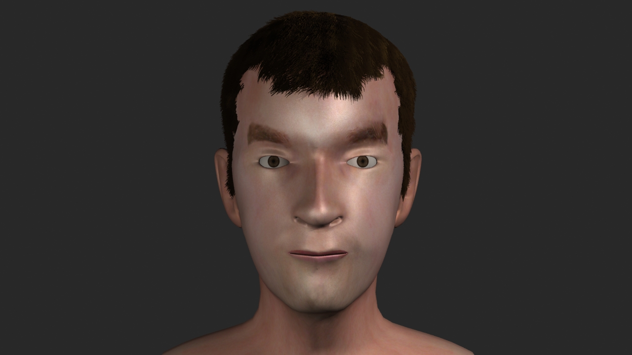
New version
I now think that the hair looks too dark but this could be changed easily by adjusting the material. I think that the second time doing the hair it has turned out better but I don't think that hair style is not as good the first time I created it.

More time could be spent on the sytling of the hair and the material that is applied to it.

Sunday, 27 November 2011

Morpher

The mopher modifier will be used to animate facial expressions for the head model. The head will be cloned and the vertices moved on them to create different facial expressions on each of the heads, these will then be linked to the morpher modifier so that they can be used to the animate the face.

I started by taking my head model and collapsing the modifier stack so that the symmetry and UVW unwrap modifiers were applied to the model. Applying the UVW unwrap modifier keeps the settings in the mesh and these can be got back by applying a unwrap UVW modifier again.


I turned off the turbosmooth modifier and cloned a series of heads to be used to create the different expressions that will be used with the morpher modifier.


I removed the turbosmooth modifiers from the cloned heads.


On the first head I decided to create the mouth open. I selected the polygons for the mouth and chin and moved it down. When using the morpher modifier you can’t change the amount of polygons, only move then about or it will not work.


On the next head closed the right eye. I selected the polygons for the bottom of the eye lid and then the top and positioned them so that the eye lid was closed.


I did the same on a different model for the other eye.


Now to apply the morpher modifier. I took the original head and added a morpher modifier below the turbosmooth.


I right clicked in one of the empty slots, selected pick from scene and then clicked on the first cloned head with the mouth open.


At the right of this is a box that can changed from 0-100. Changing this amount on will blend the effect of the mouth open model into the original model. This will allow the how much the mouth opens to be controlled.


The left and right eye opening was added in the same way. Now using the morpher modifier both the eye opening and mouth moving can be animated. They can be used at the same time or individually.

Brows up
I cloned more heads from the original and adjusted them to create the left and right brows up, smile, frown, top lip up and bottom lip down. I added these to the morpher modifier in the same way.

Smile
Frown
Top lip up
Bottom lip down
I decided that the mouth wasn't open enough so it increased this and reapplied it to the morpher.


I cloned another head to create a brows down expression this can be used with the frown morph created earlier.

Brows down
With each of these expressions applied to the model using the morpher modifier they can be used to to adjust the expressions of the face. Renders of the expression are shown below.

Normal
Smile
Eyes closed
Frown
Brows down
Bottom lip down
Top lip up
Mouth open
The different expression can be combined together using the morpher to create complex expressions. Here the brows down expression and frown are applied together.


Different morphs could be created for the different phonemes and then these could be used create lip sync animation.

Friday, 25 November 2011

Preparing the Guildhall for animation

I finished placing the objects in the scene and then modeled some display cases for the museum and the counter for the shop.


I adpated the table model to create the counter. The computer model will be placed on top of this and some shelves will be placed in the room.


And then for the display cases I used a box extruded a section and positioned it in place.


I selected the top polygon and then used insert tool to create a smaller polygon inside and then extruded this down to create the inside of the display case. I selected the vertices at the top of this section cloned and detached them and then used them to create the glass.


Once all of the objects were in place I cloned the top floor of the guildhall and the table inside and scaled it so that the whole guildhall model would fit on top of the table in the room.


I also merged the environment the was created by Hong into another version of the guildhall model so that this can be used when outside of the model is viewed in the animation.

Thursday, 17 November 2011

Slice

In the animation the guildhall will grow from the blueprints into the renovated model. To animate the building growing we will use a slice modifier and animate the slice plane.Other methods could be used such as moving the vertices that make up the model but as the model is quite complicated this would make it quite difficult to do it this way.

The slice modifier will be applied to the separate objects that make up the model so that they can be animated separately. All of the objects could be attached or grouped together and then the slice modifier applied but this would give less control over how the model can be animated.

I selected the attic part of the model, applied a slice modifier and selected remove top from the options on the modifier. By selecting remove top all of the model above the slice plane is removed, slicing through the model. When the slice plane is moved the the location where the model is sliced changes. This will allow slicing to be animated to create the building growing.

Slice
Using the slice modifier works well to create this effect but when the slice modifer cuts off the top of the model it leaves a hole where there are no polygons. To fix this a cap holes modifier can be added, this caps any holes in the model.

Cap holes
As a multi/sub object material is applied to the guildhall the material applied to the newly created faces is incorrect. To fix this a material modifier can be added, above the cap holes modifier, and then the material id set.

I also moved the uvw map modifier to the top of the modifier stack so that the materials would be mapped correctly onto the sliced object.

Material
Although this method seems to work well for many of the objects some of the more detailed objects such as the ground floor, first floor and chimney cause problems. With the chimney the cap holes modifer fills the hole in the top and with the building the model is incorrectly capped when the slice moves right near the top or bottom of the model.

The cap holes modifier works by selecting the border and then capping this hole. If an edit poly modifier is added above the slice modifier you can see that selecting the border and then selecting cap this creates the same effect. A way to solve this problem may be to remove the cap holes modifier on the objects that cause a problem and instead use an edit poly modifier and manually fill in the holes in the model by selecting the edges and then using the bridge tool.


Polygon created at the bottom of the model
The cap modifier also created a polygon at the base of the model even when the slice modifier was not applied. This was caused because there were no faces at the bottom of the walls, I fixed this by creating these faces around the bottom of the model.

Finishing the model and textures

Finishing the model and textures ready for animating.


With the stairs created I decided to create the spindles that go beneath the handrail. I used a cylinder and then used the array tool to create the rest of them.


The doors were created from boxes,  I adjusted the height and width so that they fitted in the wall sections. Next I modelled the door handles, I started with a cylinder and adjusted the shape of this by scaling sections of the cylinder. Finally I applied a turbosmooth modifier to create the final shape for the handle and added a symmetry modifier to create the one for the other side of the door.

I modeled different types of handles for the different doors in the guildhall. I applied a wood texture to the doors and a metal texture to the handles.


Finally I decided to optimize the model by removing any unneeded edges. I used target weld to join the unneeded vertices. Now the sides of the model are much simpler.

I selected the objects for the different parts of the model and created selection sets to make it easier to select them when needed. Selection sets allow you to select multiple object with one click.

To create a selection set select the objects and then type in a name for the set into the selection set box on the top toolbar and press enter. These objects can easily be selected again by selecting the name from the selection set drop-down box.

When creating the guildhall model I modelled it in separate parts. This makes it easier to see into the model as the different sections of the model can be hidden. Using selection sets the attic, first floor or ground floor can be easily selected and hidden.

Next I will look into how it can be animated to create the growing effect that we are after for the animation.

Tuesday, 8 November 2011

Guildhall windows

To create the windows I used a plane for the pane of glass and boxes for the frames. From the reference images taken of the guildhall I could see that on the top floor the windows were made up of rectangle pieces of glass but on the ground floor they were diamond shaped with diagonal frames.


I adjusted the window that I had modeled to create each of the windows in the guildhall, adjusting the size and amount of frames in each window.

Windows in place on first floor
To create the windows for the ground floor I used the method but rotated the frames so that they were diagonal.


The windows for the ground floor were trickier as it was harder to move the vertices, to adjust the size, and keep the angle of the frame correct.

Windows in place on both floors